
Ever looked at a circuit diagram and wondered what those squiggly lines or little rectangles mean? Well, that, is that, pretty common feeling. These shapes are not just random drawings; they tell a very important story about how electricity moves. Understanding the resistor electrical symbol is, in a way, like learning a secret language for anyone interested in electronics. It's truly a foundational piece of knowledge.
You see, every electronic gadget around us, from your phone to a fancy television, has tiny components working together. One of the most basic, yet incredibly important, of these parts is the resistor. My text says, a resistor can be thought of as a passive electronic component with two connection points that creates electrical resistance to the flow of current inside a circuit. It's quite simple, really, and yet, very powerful in what it helps circuits do.
So, why bother with symbols? Why not just write "resistor" everywhere? The symbols, you know, they give us a quick, universal way to show what's happening in a circuit. It’s a bit like road signs; you don't need to read a long description to know what to do. The resistor electrical symbol, then, is a quick visual cue, and honestly, it makes designing and troubleshooting circuits much, much easier. It's almost a necessity for anyone working with electricity.
Table of Contents
- What is a Resistor, Really?
- The Resistor Electrical Symbol: A Visual Language
- The Job of a Resistor: Controlling Current
- Resistance: The Core Property
- Why Resistors Are Everywhere
- Connecting the Symbol to the Science
- Frequently Asked Questions (FAQs)
- Getting Started with Resistors
What is a Resistor, Really?
Let's get down to what a resistor actually is. My text puts it plainly: a resistor is a component that puts up a fight against the flow of current. It doesn't do anything on its own, so it's called a passive component. Sounds a bit plain, doesn't it? Like, what's the big deal about something that just resists? But actually, this simple job is incredibly important for making circuits behave the way we want them to. It's pretty fundamental, really.
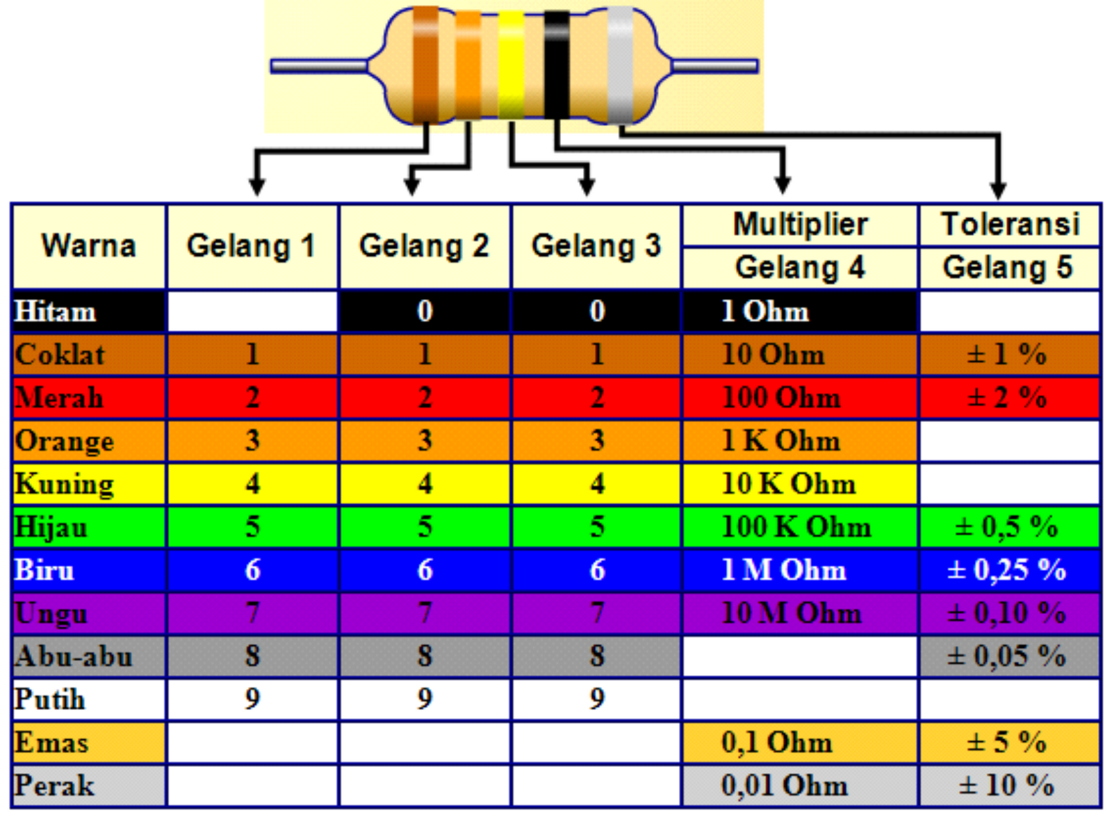
Think of electricity as water flowing through a pipe. A resistor, in this picture, is like a narrow spot or a valve that makes it harder for the water to pass through. My text also points out that a resistor is an electronic part that limits the flow of electric current in a circuit. It's built to have a certain resistance amount, measured in units called ohms, which are shown with the Greek letter omega (Ω). This specific value is what gives each resistor its unique purpose, you know.
The core idea here is that a resistor reduces the electric current. The ability of the resistor to do this current reduction is called resistance, and it's measured in those ohms. So, in simple words, it puts a check on how much current can pass through it. My text mentions that a resistor is a passive electrical component with the main job of limiting the flow of electric current. This limiting action is why they are so widely used, basically everywhere in electronics.
It's true, a resistor is a basic part used in nearly all electronic circuits. It's a passive element that resists the movement of electrons. This means it only lets a certain amount through. So, it's not just about stopping current; it's about managing it, letting just enough pass for other parts of the circuit to work correctly. It's kind of like a gatekeeper for electrons, you might say.
The Resistor Electrical Symbol: A Visual Language
Now, let's talk about the look of the resistor electrical symbol. When you draw a circuit, you don't draw a little physical resistor. Instead, you use a symbol. These symbols are a kind of universal shorthand. They help engineers and hobbyists from different places understand the same diagram without needing a language translation. It's a very clever system, in a way, that makes things much clearer.
There are, interestingly enough, two main ways to draw a resistor symbol, depending on where you are or which standard is being followed. Both of these symbols represent the same component, but they look quite different. Knowing both is a good idea, especially if you're looking at diagrams from various sources. It's almost like knowing two ways to write the same letter, you know.
The Zig-Zag Symbol (ANSI/IEEE)
One common resistor electrical symbol is the zig-zag line. This one is typically used in North America, following the ANSI (American National Standards Institute) or IEEE (Institute of Electrical and Electronics Engineers) standards. It looks exactly like it sounds: a line that goes up and down, making sharp corners, almost like a lightning bolt or a very spiky mountain range. This symbol visually suggests the idea of "resistance" or "friction" against the current, which is pretty intuitive, you know.
When you see this zig-zag symbol on a circuit diagram, it means there's a resistor placed at that spot. The number next to it will tell you its resistance value in ohms. This symbol has been around for a very long time, and it's still widely taught and used today. It's sort of a classic, really, and many people recognize it instantly.
It’s important to remember that this symbol, while common, isn't the only one out there. But for many, it's the first image that comes to mind when they think of a resistor in a circuit drawing. It's a clear, simple representation of a part that limits current flow, and it does its job well, so.
The Rectangular Symbol (IEC)
The other primary resistor electrical symbol is a simple rectangle. My text specifically mentions, "The international IEC symbol is a rectangular shape with leads at each end as shown in." This symbol is used internationally, following the IEC (International Electrotechnical Commission) standards. It's very clean, just a plain rectangle with lines extending from its shorter sides to connect to the rest of the circuit. This design is quite minimalist, you know, and some find it easier to draw.
This rectangular symbol is prevalent in Europe and many other parts of the world. Just like the zig-zag, a number written near this rectangle will indicate its resistance value. While it doesn't visually suggest "resistance" in the same way the zig-zag does, its simplicity makes it quite effective for clear diagrams. It's a different visual language, but it conveys the exact same information, which is the main thing, honestly.
Both symbols serve the same purpose: to represent a resistor. It's just a matter of which standard the diagram follows. If you're looking at a circuit from a global source, chances are you'll see this rectangular symbol. It's good to be familiar with both, so you're not caught off guard, apparently.
Why Two Symbols?
You might wonder why there are two different symbols for the same thing. It's a bit like how different countries have different ways of driving or different measurements. Historically, different regions and organizations developed their own standards for electrical symbols. Over time, some of these became more widespread, but neither completely replaced the other. So, you end up with two commonly accepted symbols for the resistor electrical symbol, basically.
It's not a problem, though. Both symbols are clear, and once you know what they mean, you can read any circuit diagram. It just means you need to be aware that there are options. It's a simple fact of how technical standards developed globally. So, if you see a zig-zag or a rectangle, just know it's a resistor, and you're good to go, you know.
The existence of two symbols really just highlights the international nature of electronics. Designers and engineers might use one over the other based on regional preference or specific project requirements. It's kind of like having different fonts for the same letter; they look different, but they mean the same thing, more or less. Understanding both just makes you a more capable circuit reader.
The Job of a Resistor: Controlling Current
So, we know what a resistor is and what its symbol looks like. But what does it actually *do* in a circuit? My text states, "Its primary function is to control the" flow of current. This control is absolutely vital. Without resistors, many circuits would simply not work, or they might even get damaged. They are, quite honestly, unsung heroes of the electronic world, you know.
Imagine you have a light-emitting diode, a small LED. If you connect it directly to a battery, too much current might flow through it, causing it to burn out. A resistor placed in series with the LED will limit that current to a safe level, allowing the LED to light up brightly without damage. This current limiting is one of their most common uses. It's a very practical application, as a matter of fact.
My text also mentions that resistors play a critical role in functions like dividing voltage. Yes, they can be used to create specific voltage levels in a circuit, which is super useful for powering different parts that need different amounts of electrical push. For instance, if you have a 9-volt battery but need 3 volts for a sensor, resistors can help you get that precise voltage. It's pretty clever, actually, how they manage this.
They are used in electronic circuits for voltage management in many ways. This can involve reducing a higher voltage to a lower one, or setting specific voltage points for other components to work from. This ability to manipulate voltage and current is why the resistor electrical symbol appears so frequently on circuit diagrams. They're just that versatile, you see.
Resistance: The Core Property
The key characteristic of a resistor is, naturally, its resistance. My text notes, "Its property to resist the flow of current is called resistance, expressed in." This property is what defines how much the resistor will "fight" the current. A higher resistance value means it puts up a bigger fight, allowing less current through. A lower resistance value means it's less restrictive, letting more current pass. It's a pretty straightforward relationship, honestly.
My text further clarifies that the resistor's ability to reduce the current is called resistance and is measured in units of ohms, with the symbol Ω. This unit, the ohm, is named after Georg Simon Ohm, a German physicist who studied the relationship between voltage, current, and resistance. So, when you see a resistor marked "100 Ω," it means it has 100 ohms of resistance. It's a very precise measurement, you know.
Understanding ohms is crucial because it tells you exactly how much current a resistor will allow to pass, given a certain voltage. This is governed by Ohm's Law, a fundamental principle in electronics. Knowing this helps you pick the right resistor for the job, ensuring your circuit works as intended without any issues. It's pretty much the heart of what a resistor does, you might say.
The value of resistance can range from very small (a few ohms) to very large (millions of ohms, or megaohms). Each value has a specific purpose in a circuit, whether it's protecting delicate components, setting signal levels, or creating timing delays. The resistor electrical symbol on a diagram will always be accompanied by this crucial ohm value, which is really what makes it useful, so.
Why Resistors Are Everywhere
If you take apart almost any electronic device, you're pretty much guaranteed to find resistors inside. My text says, "Resistor is basic component that is used in all the electronic circuits." This isn't an exaggeration. They are truly foundational. Their simplicity and versatility make them indispensable for circuit designers. They're like the basic building blocks, you know, that everything else rests upon.
From controlling the brightness of an LED, as mentioned before, to setting the gain of an amplifier, or even just pulling a signal line to a known state, resistors are constantly at work. They help ensure that the right amount of current flows to the right place, preventing damage and making sure signals are clear. They are, in a way, the traffic cops of the electronic world, managing the flow of electrons. It's a rather important job, actually.
Their passive nature means they don't need a separate power source to do their job, which simplifies circuit design. They just sit there, doing their resistance thing, quietly and reliably. This reliability, combined with their low cost and wide availability, means they are, basically, everywhere. You'd be hard-pressed to find a circuit without at least one resistor electrical symbol on its schematic.
They are quite literally in everything from your computer's motherboard to the tiny circuit in a remote control. Their ability to limit current and divide voltage means they are essential for making different parts of a circuit communicate safely and effectively. It's amazing how such a simple component can have such a profound impact on how complex electronics function, you know.
Connecting the Symbol to the Science
So, how does the resistor electrical symbol connect to the actual science of how resistors work? Well, the symbol is a visual shorthand for the component's function. When you see that zig-zag or rectangle, your mind should immediately go to the idea of "resistance" and "current limiting." It's a powerful mental link that helps you understand the circuit's purpose at a glance. It's pretty efficient, really.
Circuit diagrams are like blueprints for electronic devices. Just as an architect uses symbols for doors and windows, an electronics designer uses symbols for resistors, capacitors, and other parts. These symbols, including the resistor electrical symbol, allow for clear communication of complex ideas in a standardized way. This standardization is key for collaboration and for troubleshooting, obviously.
Learning these symbols is the first step towards truly understanding how electronic circuits are put together and how they operate. It moves you beyond just seeing lines and shapes to seeing the flow of electricity, the control points, and the relationships between different components. It's almost like learning to read music; once you know the notes, you can understand the song, you know.
Every time you spot a resistor symbol, you're looking at a place where current is being managed, where voltage might be adjusted, or where a signal path is being influenced. It's a reminder of the resistor's fundamental role in ensuring the circuit operates safely and correctly. It's a simple drawing, but it represents a critical function, which is pretty cool, actually.
Frequently Asked Questions (FAQs)
What are the two symbols for a resistor?
There are two main symbols you'll typically see for a resistor. One is the zig-zag line, often used in North America under ANSI/IEEE standards. The other is a simple rectangle, which is the international IEC standard symbol. Both represent the same electronic component, just in different visual styles. It's a bit like different ways of writing the same letter, you know, but they both mean the same thing, basically.
What does the resistor symbol represent?
The resistor electrical symbol represents a passive electronic component whose main job is to limit or control the flow of electric current in a circuit. It signifies a point in the circuit where resistance is intentionally added to manage the electrical flow. It's a visual cue for a part that puts a check on current, and it's pretty clear about that, too it's almost.
Why is a resistor called a passive component?
A resistor is called a passive component because it doesn't need an external power source to do its job, and it doesn't actively generate or amplify electrical energy. Instead, it simply consumes or dissipates energy, usually as heat, as it resists current flow. My text says, "It doesn’t do anything actively, so it’s called a passive component." It just sits there and does its thing, you know, without needing a push.
Getting Started with Resistors
Understanding the resistor electrical symbol is a great first step into the wider world of electronics. It's a bit like learning your ABCs before you can read a book. Once you grasp this basic concept and its visual representation, you're well on your way to making sense of more complex circuit diagrams. It's a skill that will serve you well, apparently, in any electronics project you might take on.
So, the next time you see that zig-zag or rectangle on a circuit drawing, you'll know exactly what it means: a resistor, quietly doing its job of managing current. This foundational knowledge is truly valuable for anyone curious about how gadgets work, or for those looking to build their own. It's pretty exciting, actually, to start connecting these symbols to real-world functions.
To learn even more about how different components work together, you might want to explore resources like All About Circuits, which offers a lot of helpful information. Keep exploring, keep learning, and you'll find that the world of electronics becomes much clearer, and honestly, a lot more fun. It's a continuous journey of discovery, you know.
Detail Author:
- Name : Elissa Stark
- Username : mariano04
- Email : wgerhold@gmail.com
- Birthdate : 1992-11-27
- Address : 847 Johnny Overpass Schuppeland, ND 61300
- Phone : 310-856-6946
- Company : Rolfson-Hodkiewicz
- Job : Food Servers
- Bio : Ex excepturi incidunt voluptas alias quia. Et amet omnis quis vel nisi architecto. Doloremque perspiciatis expedita impedit non ut saepe. Natus iusto repellendus eligendi architecto.
Socials
facebook:
- url : https://facebook.com/bettie6487
- username : bettie6487
- bio : Vero aut qui ut animi porro. Exercitationem praesentium vitae omnis quia.
- followers : 660
- following : 1151
tiktok:
- url : https://tiktok.com/@bfritsch
- username : bfritsch
- bio : Dolorum qui quasi facilis aut impedit.
- followers : 1446
- following : 41
linkedin:
- url : https://linkedin.com/in/fritsch2020
- username : fritsch2020
- bio : Autem sed id fuga.
- followers : 1084
- following : 2786
